New Paragraph
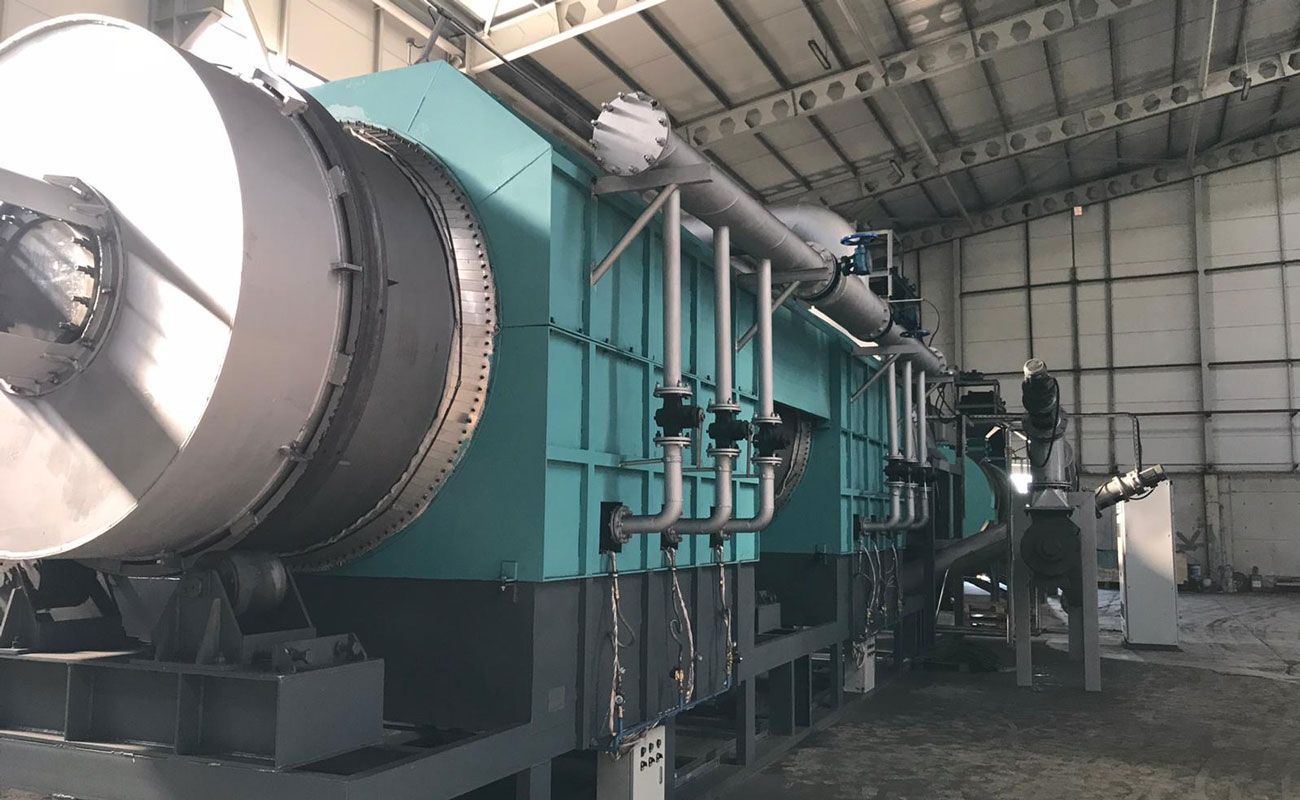
A pyrolysis plant, which is designed to thermochemically break down organic materials in the absence of oxygen, faces multiple operational challenges. These challenges must be understood and addressed to ensure continuous and efficient processing. The primary goal is to achieve stable, cost-effective operations with minimal downtime, as any disruptions can incur substantial financial losses and affect product quality. There are various factors that influence the continuous operation of pyrolysis equipment, ranging from feedstock characteristics to equipment design and process management. Feedstock Variability and Its Impact Consistency of Feedstock Quality One of the most significant factors affecting the continuous operation of a continuous pyrolysis plant is the variability in feedstock quality. Feedstocks, whether biomass, plastics, or tires, may vary in moisture content, particle size, and chemical composition. These variations directly influence the pyrolysis process, which is highly sensitive to input material characteristics. Inconsistent feedstock quality can lead to inefficient heat transfer, incomplete pyrolysis reactions, or operational blockages. The moisture content of the feedstock, for instance, requires additional energy to vaporize the water during pyrolysis. This can reduce the efficiency of the plant and increase energy consumption. Similarly, large or irregularly shaped particles can cause uneven heating and delays in the decomposition process. To achieve continuous operation, feedstock preprocessing is vital, including drying, grinding, and homogenization. Impurities in Feedstock Another challenge is the presence of contaminants in the feedstock. In the case of plastic or mixed waste materials, impurities like metals, glass, and other non-organic materials can damage the pyrolysis plant’s internal components. These impurities can clog reactors, interfere with gas flow, and result in premature wear and tear of equipment. It is essential to implement an effective sorting and cleaning system before the feedstock enters the reactor to avoid these issues.
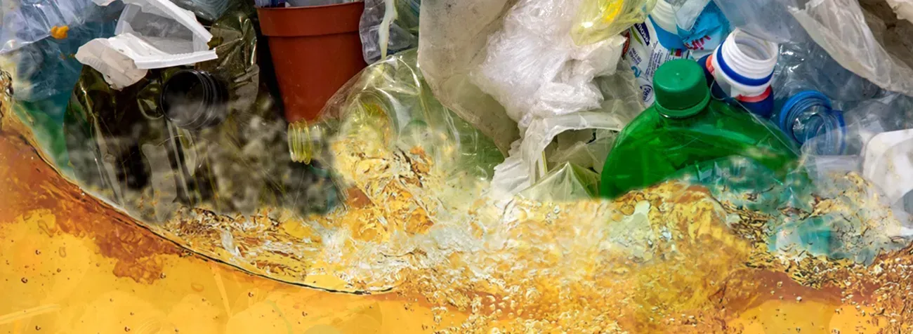
Plastic pyrolysis projects offer a promising solution for managing plastic waste while producing valuable products like fuel oil, gas, and carbon black. However, like any large-scale industrial process, they come with a variety of risks. These risks span across technical, environmental, regulatory, and financial dimensions, and their careful evaluation is crucial to the success and sustainability of such projects. A comprehensive risk assessment allows stakeholders to address potential challenges proactively and develop effective mitigation strategies. Technical and Operational Risks Feedstock Variability and Quality The type and quality of plastic feedstock can vary significantly depending on the source and collection method. Variations in plastic composition, contaminants, and moisture content can negatively impact the efficiency and consistency of the pyrolysis process. Feedstock quality issues may lead to operational instability, lower yields, or the production of suboptimal by-products. To mitigate these risks, it is important to establish robust feedstock qualification procedures. This includes implementing sorting, cleaning, and drying steps before processing to ensure a consistent material input. Technological solutions such as automated sorting systems can help standardize the feedstock quality entering the plastic pyrolysis plant . Process Control and Stability Pyrolysis is a complex thermal decomposition process, and maintaining consistent temperature, pressure, and residence time is crucial for ensuring high-quality outputs. Variations in these parameters can lead to suboptimal product formation, equipment wear, or even safety hazards. For example, fluctuations in temperature can lead to incomplete pyrolysis, reducing the yield of valuable products like fuel oil or carbon black. To manage these risks, it is vital to incorporate advanced control systems with real-time monitoring and automated adjustments. Using sensors, feedback loops, and predictive maintenance can help keep the pyrolysis process within optimal operating conditions, reducing downtime and enhancing product consistency. Scale-Up Challenges While pilot projects may perform well under controlled conditions, scaling up to a larger pyrolysis plant introduces several challenges. Scaling typically exposes issues related to heat distribution, material handling, and reactor design. Larger-scale operations may experience difficulties in maintaining uniform temperature profiles or achieving optimal gas recovery. Risk mitigation in scaling can be achieved by performing thorough feasibility studies, engaging in small-scale pilot testing, and incorporating modular designs that allow for iterative scaling. This ensures that operational challenges are addressed before they become critical at full scale.
The body content of your post goes here. To edit this text, click on it and delete this default text and start typing your own or paste your own fromPlastic pyrolysis occupies a contested space between waste treatment, fuel production, and material recovery. The technical distinction that increasingly defines its classification is not the presence of thermal cracking itself, but the composition of its liquid output. Specifically, naphtha yield has become the decisive metric separating chemical recycling from energy recovery. This distinction is grounded in petrochemical logic, refinery compatibility, and carbon accounting discipline. Chemical Recycling as a Feedstock Substitution Concept Material Loop Closure Versus Energy Dissipation Chemical recycling is fundamentally about loop closure. The objective is to convert post-consumer or post-industrial plastic waste into molecular intermediates that can re-enter polymer manufacturing. In contrast, processes that primarily generate fuels merely redirect carbon toward combustion, terminating its material lifecycle. Naphtha occupies a privileged position in this framework. It is not an end-use fuel by design, but a petrochemical feedstock. When plastic pyrolysis oil approximates naphtha in composition and functionality, it can displace virgin fossil-derived streams in steam crackers and polymerization units. Why Product Identity Matters More Than Process Labeling Thermal depolymerization alone does not constitute chemical recycling. The decisive factor is whether the output can be used as a chemical raw material without downcycling. Regulators, certification bodies, and polymer producers increasingly evaluate outputs, not process descriptions. A plastic to oil machine producing high aromatic fuel oil may be technologically sophisticated, yet still fall outside chemical recycling definitions. Conversely, a system optimized for naphtha-range hydrocarbons aligns directly with petrochemical value chains. a different source.
Plastic-to-fuel and plastic-to-chemical conversion technologies have accelerated in recent years, and regulatory scrutiny has intensified at the same pace. A modern pyrolysis plant processing post-consumer or industrial plastics must satisfy a multi-tiered compliance structure involving emissions governance, feedstock control, occupational safety, hazardous-material management, and product-quality oversight. Regulatory assessment is not a single checkpoint. It is an integrated evaluation that begins at the design phase and persists throughout the facility’s operational life. Short sentences reinforce clarity. Compliance safeguards operational viability. Frameworks Governing Environmental Authorization Air Emission Standards One of the central compliance dimensions for any plastic pyrolysis facility is air-quality permitting. Thermal depolymerization generates a complex profile of vapors, including volatile organic compounds, particulate matter, and trace halogenated compounds depending on feedstock composition. Regulatory oversight typically mandates continuous emission monitoring, dust abatement, and strict adherence to combustion efficiency thresholds. Advanced condensation and scrubbing systems must demonstrate quantifiable removal efficiency. A plastic pyrolysis plant seeking approval must present validated emissions modeling, measurement protocols, and equipment specifications capable of meeting regional environmental statutes. Waste Residue Classification Solid residues—primarily char and inert ash—may fall under non-hazardous or hazardous classification depending on regulatory jurisdiction and chemical analysis. The classification determines allowable storage duration, disposal pathways, and handling requirements. Authorities often require leachate tests, heavy-metal quantification, and characterization of persistent organic pollutants prior to issuing a facility permit. Feedstock Compliance and Traceability Source Verification Plastic waste streams must be traceable, properly documented, and compliant with accepted material categories. Unauthorized or contaminated feedstock can trigger regulatory violations. Many jurisdictions prohibit the processing of PVC-rich materials without advanced dechlorination systems because uncontrolled thermal degradation may produce corrosive or harmful emissions. A robust feedstock verification protocol ensures the plastic to fuel machine receives plastics aligned with its engineered tolerances. This includes documentation trails, contamination thresholds, and periodic third-party audits. Inventory Control Inventory logs, batch records, and storage conditions are routinely inspected to verify compliance with waste-management standards. Traceability systems must reflect real-time data, including origin, composition, and processing date. This minimizes discrepancies that could affect regulatory reporting or introduce environmental risk. Occupational and Process Safety Requirements Hazardous Area Classification A pyrolysis facility contains high-temperature reactors, pressurized vessels, hydrocarbon vapors, and flammable gases. Regulatory inspectors examine hazard zoning, grounding systems, ventilation, and explosion-proof infrastructure. Safety protocols must be codified and demonstrated through operational readiness reviews. Short sentences emphasize urgency. Safety governs continuity. Training and Competency Operators must exhibit documented proficiency in thermal process control, emergency shutdown, leak detection, and gas-handling procedures. Annual refresher training is often mandated. Compliance inspections typically require training logs, certifications, and drills demonstrating preparedness for equipment malfunctions or feedstock anomalies. Mechanical Integrity and Equipment Verification Reactor and Pressure System Certification Inspections assess whether reactors, condensers, pipelines, and pressure vessels meet manufacturing standards. Weld quality, metal thickness, corrosion resistance, and pressure-relief systems must align with regulated engineering codes. Inspectors often request third-party inspection reports, hydrostatic test results, and material certification sheets to demonstrate mechanical integrity. Preventive Maintenance Documentation Regulatory authorities expect structured maintenance plans. These plans include lubrication schedules, instrument calibration, sensor verification, and replacement intervals for key components such as seals, valves, and burners. Documentation must be complete, chronological, and readily accessible for auditing. Chemical Handling and Storage Oversight Product Storage Compliance The output of a pyrolysis plant—oil, wax, and non-condensable gas—falls under chemical storage regulation. Storage vessels must be engineered to prevent leakage, overpressure events, and ignition risks. Secondary containment, fire suppression systems, and spill-response infrastructure are mandatory in most jurisdictions. Hazard Communication Systems Safety data sheets (SDS) and labeling requirements apply to all stored materials. Regulators verify that employees can quickly identify hazards, understand exposure limits, and follow emergency procedures. This ensures alignment with chemical-safety frameworks such as GHS (Globally Harmonized System). Energy Integration and Emission Control Validation Combustion Optimization Non-condensable gas used as an internal heat source must be combusted efficiently to meet emission benchmarks. Regulators examine burner performance, oxygen ratios, heat-distribution profiles, and stack-gas measurements. Demonstrated combustion stability is essential to minimize pollutants and ensure thermal efficiency. Secondary Treatment Systems Scrubbers, activated-carbon filters, and catalytic converters require performance testing to validate their removal efficiency. Compliance reviews often involve field measurements and verification of reagent dosing systems. Thermal oxidizers, where used, must meet destruction-removal efficiency (DRE) targets. Documentation, Reporting, and Data Integrity Periodic Reporting Obligations Environmental authorities typically require quarterly or annual reports detailing emissions data, waste-handling volumes, product output, and maintenance activities. The data must be precise, consistent, and derived from calibrated instrumentation. Inaccurate reporting exposes the facility to administrative penalties. Real-Time Monitoring Systems Modern compliance regimes increasingly adopt digital monitoring expectations. Supervisory control systems capable of logging temperature, pressure, flow, and emission metrics provide traceable datasets. Regulators evaluate the reliability of these systems and the mechanisms for detecting anomalies. Advancing Compliance Readiness for Plastic Pyrolysis Operations A comprehensive compliance assessment ensures that a plastic pyrolysis facility operates within environmental, procedural, and safety parameters defined by regulatory authorities. This multilayer evaluation—spanning feedstock screening, emissions governance, mechanical integrity, occupational safety, and data transparency—fortifies operational resilience. Through rigorous adherence to these standards, a pyrolysis plant establishes long-term credibility, minimizes risk exposure, and ensures sustainable alignment with the evolving regulatory landscape.

Rice husk is inherently rich in inorganic constituents, especially silica. During thermochemical conversion, these mineral fractions accumulate as ash and exert substantial influence on process kinetics. In a pyrolysis plant, elevated ash content alters the heat-transfer profile of the biomass bed. Ash acts as a thermally inert component, absorbing heat without contributing to volatilization. This induces slower temperature escalation, particularly in dense feed layers. As a result, the char yield, volatile evolution rate, and reaction uniformity all shift in response to the mineral burden present in the husk. Ash with high silica crystallinity further limits internal heat penetration. Crystalline silica reflects heat more readily than amorphous forms, generating localized cool zones within the feed matrix. These zones restrict the release of condensable vapors, thereby reducing oil yield efficiency. Impact on Catalytic Behavior and Reaction Pathways Mineral-Catalyzed Cracking The inorganic oxides present in rice husk ash exhibit catalytic tendencies. Potassium, calcium, and magnesium promote secondary cracking reactions that fragment long-chain volatiles into lighter compounds. This transformation can enhance gas production while diminishing the quantity of liquid products. The catalytic effect becomes pronounced in high-ash feedstocks, subtly modifying the thermochemical pathways inside a rice husk carbonizer . Influence on Char Microstructure Ash content influences the formation of carbonaceous structures. Elevated mineral load introduces nucleation sites that disrupt carbon layer alignment. The resulting char exhibits lower structural uniformity and reduced adsorption potential. This altered microstructure affects both downstream utilization and the thermal feedback loop within the reactor. Heat-Transfer Dynamics and Bed Permeability Rice husk, despite its fibrous geometry, experiences reduced bed permeability when ash proportion increases. Ash particles fine enough to fill interstitial spaces constrict natural air and vapor channels. Restricted permeability slows vapor evacuation and prolongs retention times. This can lead to secondary char-to-vapor interactions, modifying product distribution. Heat-transfer resistance intensifies under these conditions. In systems operating at high throughput, this resistance can create temperature stratification. Thermal gradients complicate reactor control and require more frequent adjustments to feed rate, heating power, and residence time. Influence on Liquid and Gas Yield Profiles Liquid Yield High-ash biomass generally produces lower liquid output. The inorganic fraction, by inhibiting uniform thermal propagation, suppresses the release of condensable volatiles. Additionally, catalytic cracking mediated by potassium salts reduces the fraction of heavy oils formed during primary decomposition. Gas Yield Syngas and non-condensable gases typically increase when ash levels are elevated. Mineral-induced cracking accelerates the formation of CO, CO₂, and small hydrocarbons. Although this may improve the energy balance of a pyrolysis machine for biochar , it reduces the commercial value of liquid products. Char Yield Char production may remain stable or increase slightly, depending on the ash-to-carbon ratio. High ash dilutes the available fixed carbon and simplifies the carbonization pathway, sometimes resulting in a larger char mass with diminished calorific value. Operational Considerations for High-Ash Feedstocks Reactor Fouling Ash with a high silica fraction can adhere to reactor walls or heating surfaces. Silica slags form at elevated temperatures, posing a risk of fouling and heat-transfer obstruction. Periodic maintenance becomes essential to mitigate performance decline. Feedstock Pre-Conditioning Screening, demineralization, and controlled blending reduce ash-related inefficiencies. Some operators introduce pre-washing stages to remove soluble salts, thereby diminishing catalytic interference during pyrolysis. Temperature and Residence Time Adjustment High-ash feedstocks necessitate optimized operating conditions. Increased temperature setpoints or extended residence times compensate for slower thermal penetration. These adjustments secure consistent decomposition and stabilize product quality. Integrated Performance Outlook The ash characteristics of rice husk exert pervasive influence over pyrolysis behavior. They regulate heat-transfer efficiency, catalytic reactivity, product distribution, and reactor stability. Effective management of these mineral components enables a pyrolysis plant to maintain robust operational performance while handling diverse biomass profiles.
Plastic pyrolysis has become a prominent pathway for transforming heterogeneous polymer waste into liquid hydrocarbons, synthetic gas, and char. Yet the rapid expansion of this sector has brought regulatory scrutiny that is more intricate than that applied to conventional waste-processing technologies. A modern pyrolysis plant operating on plastic feedstock must contend with rigorous environmental governance, safety directives, chemical-handling regulations, and product-classification standards. These layers of oversight create a multifaceted compliance environment that operators must navigate with precision. Environmental Permitting and Emission Governance Air Emission Thresholds and Monitoring The thermal decomposition of plastics generates a diverse array of volatile compounds. Regulators therefore impose strict emission thresholds for particulate matter, nitrogen oxides, acid gases, and trace organic pollutants. Continuous emission monitoring systems are frequently mandated for stack outlets, requiring calibrated sensors, certified analyzers, and authenticated data-logging systems. Even minor exceedances can trigger corrective action plans, operational limits, or mandatory system upgrades. This elevates the importance of robust gas-stream conditioning, including thermal oxidizers, scrubbers, and activated-carbon filtration. Wastewater and Condensate Oversight Condensed pyrolysis liquids often contain phenolics, PAHs, and chlorine-bearing compounds. Discharging or treating these streams requires compliance with hazardous-waste water regulations. Facilities must maintain controlled segregated containment, leak-detection protocols, and approved disposal partnerships. Regulatory audits focus on storage integrity and traceability of every liquid by-product. Feedstock Classification and Traceability Obligations Plastic waste streams vary widely in chemical composition. Regulators therefore require formalized feedstock characterization to prevent processing of prohibited materials such as PVC, fluoropolymers, or contaminated industrial waste. A plastic pyrolysis plant must document: Polymer identification and sorting procedures Contamination thresholds Moisture and additive content Source verification for imported waste Failure to maintain feedstock traceability can result in penalties, feedstock rejection, or reclassification of the facility’s operational permit. Product Registration and Market Compliance Fuel and Chemical Output Certification The liquid oil derived from plastic pyrolysis may be considered a fuel precursor, chemical intermediate, or waste-derived product, depending on jurisdiction. Each classification leads to distinct compliance pathways. Some regions require fuel-quality certificates, sulfur analysis records, and ignition-parameter testing. Hazardous Material Handling If pyrolysis liquid is designated as hazardous, operators must comply with strict labeling, transport, and storage standards. Secondary containment, fireproof materials, and controlled ventilation become mandatory. These requirements influence layout planning, capital expenditure, and insurance obligations. Worker Protection and Operational Safety Stringent occupational-safety directives apply to pyrolysis systems due to high-temperature reactors, pressurized equipment, and volatile liquids. Operators must implement: Explosion-prevention designs compliant with ATEX or equivalent standards Thermal-insulation specifications to reduce burn hazards Gas-detection networks for early leak identification Emergency-venting systems to prevent reactor overpressure Training documentation and periodic hazard-analysis updates are compulsory. Safety non-compliance can immediately halt production. Circular-Economy Certification and Transparency Requirements Plastic-to-fuel and plastic-to-chemical projects increasingly require certification under circular-economy or recycled-content frameworks. These systems mandate detailed material-balance calculations, verification of recycled mass attribution, and third-party auditing. A pyrolysis plant must therefore maintain digital tracking tools capable of validating the recycled origin of output products. This creates additional administrative and technological burdens but is essential for accessing premium markets and regulatory incentives. The Compliance Landscape as a Determinant of Project Viability Plastic pyrolysis is technically feasible and commercially promising, yet regulatory complexity remains one of its strongest gating factors. Environmental controls, traceability obligations, and safety expectations form a tightly interlinked compliance architecture. Operators who integrate monitoring systems, transparent data workflows, and high-spec emission controls into facility design will find themselves positioned for long-term stability. Those who underestimate compliance pressures risk operational delays, market exclusion, or costly retrofits.
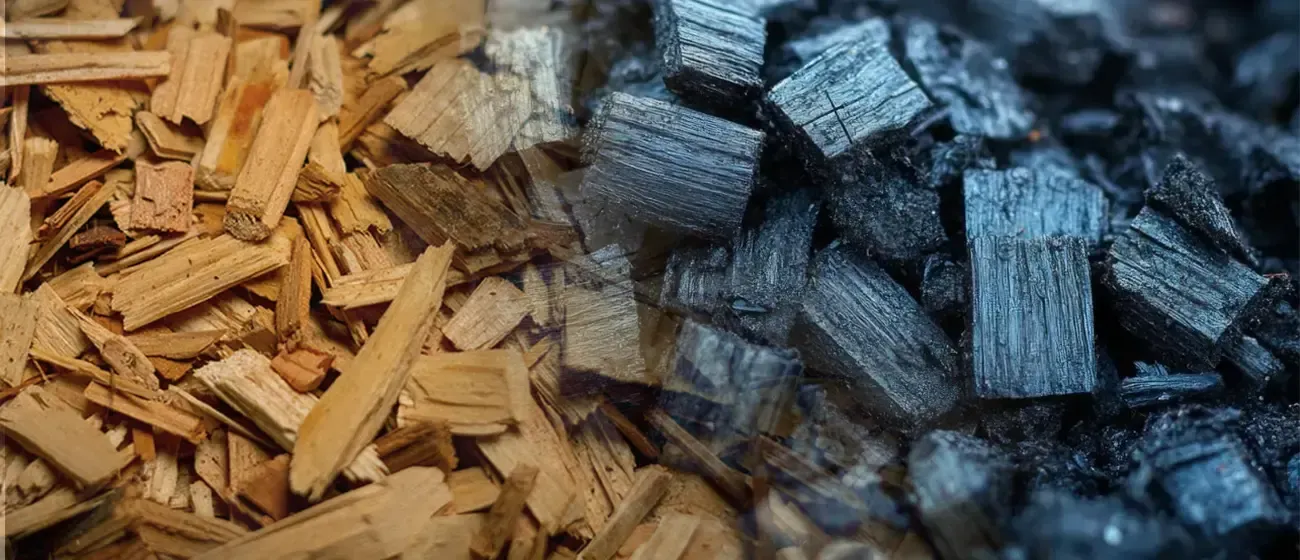
Waste wood—often viewed merely as construction debris, forestry residue, or discarded pallets—possesses intrinsic attributes that make it one of the most efficient inputs for engineered biochar production. Its lignocellulosic structure, relatively low ash content, and predictable moisture profile enable consistent thermochemical behavior. When processed in a modern pyrolysis plant , waste wood transitions from a bulky disposal liability into a high-purity carbon material with stable physical and chemical properties. This transformation highlights its suitability as a preferred feedstock in biochar manufacturing systems. Structural Advantages of Lignocellulosic Biomass The molecular composition of waste wood plays a decisive role in determining its biochar yield and stability. Wood contains three major biopolymers—cellulose, hemicellulose, and lignin—each decomposing at distinct temperature intervals. Cellulose contributes to volatile release, influencing pore formation. Hemicellulose decomposes quickly, affecting overall yield. Lignin , with its aromatic complexity, enhances char stability and fixed carbon content. High lignin concentration in hardwood waste, such as oak or walnut, supports the formation of durable carbon matrices with superior adsorption and soil-ameliorating properties. Softwood waste, although lighter in density, offers quicker thermal degradation and reduced contamination risk. The versatility across wood types ensures reliable process control in any wood charcoal making machine configured for biochar output.
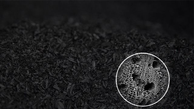
The increasing demand for cost-efficient and low-emission energy sources has prompted industries to explore biomass-derived alternatives to fossil fuels. Among these, rice husk charcoal produced from pyrolysis technology is emerging as a viable and sustainable substitute for conventional boiler fuel. Its combustion characteristics, calorific value, and carbon-neutral profile position it as a critical element in the transition toward cleaner industrial heating solutions. Conversion of Rice Husk into Charcoal Rice husk, an abundant agricultural residue, is often underutilized or disposed of through open burning, releasing harmful pollutants. Through thermochemical decomposition in a rice husk carbonizer , this waste can be converted into high-quality charcoal. The pyrolysis process occurs in an oxygen-limited environment, typically at temperatures between 400°C and 600°C. During this process, volatile compounds are vaporized, leaving behind a carbon-dense solid with high energy content. The resulting rice husk charcoal is lightweight, porous, and possesses a heating value typically ranging between 4,000 and 5,000 kcal/kg, depending on process conditions. These properties make it suitable for industrial boiler applications that demand steady and efficient thermal output.
Wood charcoal production via pyrolysis has gained prominence as a sustainable method for waste management and carbon sequestration. However, like other biomass pyrolysis processes, it presents several challenges, particularly concerning the management of tar. Tar, a byproduct of the thermal decomposition of wood, is a sticky, volatile substance that can create operational difficulties in pyrolysis plants. Effective tar control is essential not only to improve the efficiency of the process but also to ensure environmental compliance and reduce operational costs. The Role of Tar in Wood Pyrolysis During the pyrolysis of wood, organic material is heated in an oxygen-limited environment, resulting in the breakdown of biomass into gases, liquids, and solid residues (charcoal). Tar forms primarily in the liquid phase of pyrolysis, as complex organic compounds break down and condense. The presence of tar in charcoal making machine creates several operational challenges, including clogging of pipes, reduced efficiency of gas combustion, and the need for additional cleaning and maintenance procedures. Furthermore, unprocessed tar can lead to environmental pollution if not properly managed. While tar is often seen as a nuisance in pyrolysis systems, it also contains valuable hydrocarbons that can potentially be converted into fuel or other valuable chemicals. Therefore, efficient tar management in pyrolysis plants not only addresses operational difficulties but can also open up opportunities for value recovery.